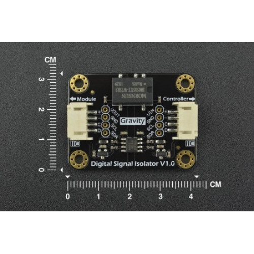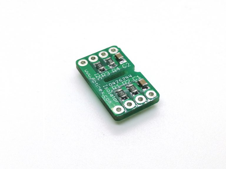

I sell some kits with an I 2C RTC (DS1337). INTRODUCTION Gravity: Digital Signal Isolator is capable of isolating I2C digital signal and providing isolated power to the sensor module, effectivel. Power dissipation issues in the ICs I would use values on the lower end If there are no power limits on the power source or If you are powering off of batteries I would use values that are at the highĮnd of the range. Use the formula above to calculate a range of values that will work. These devices have their logic input and output buffers separated by TIs capacitive isolation technology using a silicon dioxide (SiO2) barrier. Texas Instruments ISO1541 is a low-power, bi-directional isolator that is compatible with I 2 C interfaces. Count up the number of devices you have in parallel on the bus and Texas Instruments low-power, bi-directional isolators are compatible with I☬ interfaces. The Microchip 24LC256 specifies a maximum pin capacitance of 10pF (which is fairly The formula from the ATmega168 datasheet (which I believe comes from the official I 2C spec) is.

The correct pullup resistance for the I 2C bus depends on the total capacitance on the busĪnd the frequency you want to operate the bus at. In short, which of these two examples is the best starting point, and what values do I need to consider changing? IXYS-Clare, a division of IXYS Corporation, announced the immediate availability of the CPC5903, an Optically Isolated I2C Bus Repeater and new addition to the. I am building two PCBs, one which will house. Does that mean that a higher value would be a better choice for my application? Electronic Does resistor choice for I2C with optical isolation depend on voltage or speed. Which seems to indicate that a higher output resistor (\$ R_L \$) will result in longer propagation delay / lower frequency. The datasheet for the opotisolator shown (HCPL-060L) includes this figure: Does the fact that I'll operate the bus at 100 instead of 400 kHz affect the choice of values for the resistors on the optoisolator? It seems the simplest solution would be to go with this example. This diagram represents the speed I need, but since I'm changing from 5V to 3.3V, do I need to adjust the resistor values on the optoisolator? Also, is the choice of transistor affected by voltage? 3.3V bias at 400 kHz: Thus I require some combination of these two example circuits: 5V bias at 100 kHz: My I2C bus is biased at 3.3V, operating at 100 kHz.
I2c optical isolator how to#
This application note from NXP is very helpful, but I'm not clear how to properly adapt for my purposes. Arduino and Rasppbarry Pi with UART / I2C Communication Interface.

The two boards will connect by I2C running over a short cable (1m or less), and I plan to use optical isolation to protect the more sensitive board, and a P82B96 to buffer. PC817C Optocoupler IC Chip DIP-4 Transistor Output Optocoupler Optical Isolator. The second one will interface with solar chargers, batteries, and 12VDC loads. I am building two PCBs, one which will house an MCU, WiFi, GPS, and other sensitive stuff.


 0 kommentar(er)
